For the Tremec T56 reverse lockout solenoid, use the following connector: GM # 12101857 or ACDelco # PT249
How to make a timer circuit that will enable one handed T56 shifting into reverse.
The T56 transmission has an electric solenoid reverse lockout mechanism. But I have been unhappy with using a pushbutton switch to activate the solenoid in order to get the car into reverse because it is a two-handed operation, reaching over to a switch with my left hand and shifting into reverse with my right. I looked without success for a shift knob with a pushbutton switch that I liked.
So I decided to develop a timer circuit that can drive the reverse lockout, so I can hit the switch with my right hand and then have some time to get the car into reverse before the solenoid returns to the lockout position. The circuit has been in my car for years now, and I find it extremely convenient.
Many people who do not want to build a circuit have asked me to build and sell this unit, so I now sell it here: www.accutach.com
I tried a resistor/capacitor circuit which formed an RLC circuit, but I found that the capacitors needed to be far too big to be practical, so I decided I needed to go to a design based on an integrated circuit called a 555 Timer chip. I needed to design a circuit that works with a momentary on pushbutton and close a relay for a few seconds. I decided that it would be good to target a 1-20 second interval.
The design
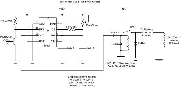
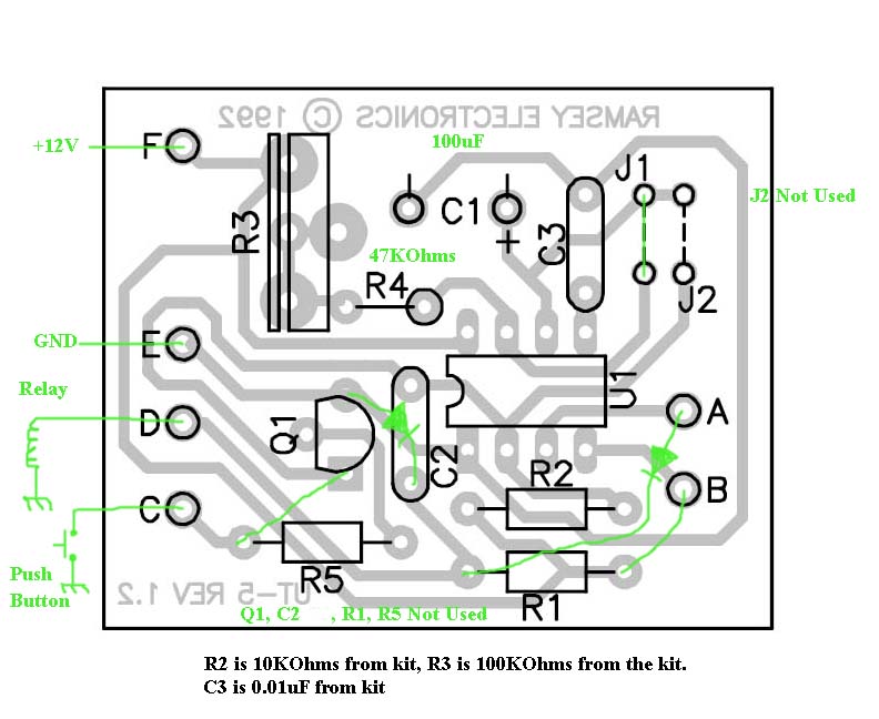
This is the design I developed:
Then, I did a search on the internet and I found that there is a $10 kit available that can be tweaked a bit to work. The kit is from a company called Ramsey Electronics (http://www.ramseyelectronics.com/). The kit is called the “UT5” (http://www.ramseyelectronics.com/cgi-bin/commerce.exe?preadd=action&key=UT5)
In the South Bay Area, there are two distributors of this kit: Frys and Halted Supply Company. I bought mine from HSC (http://www.halted.com/). (http://www.halted.com/commerce/catalog/product.jsp?product_id=13875&czuid=1207715779892)
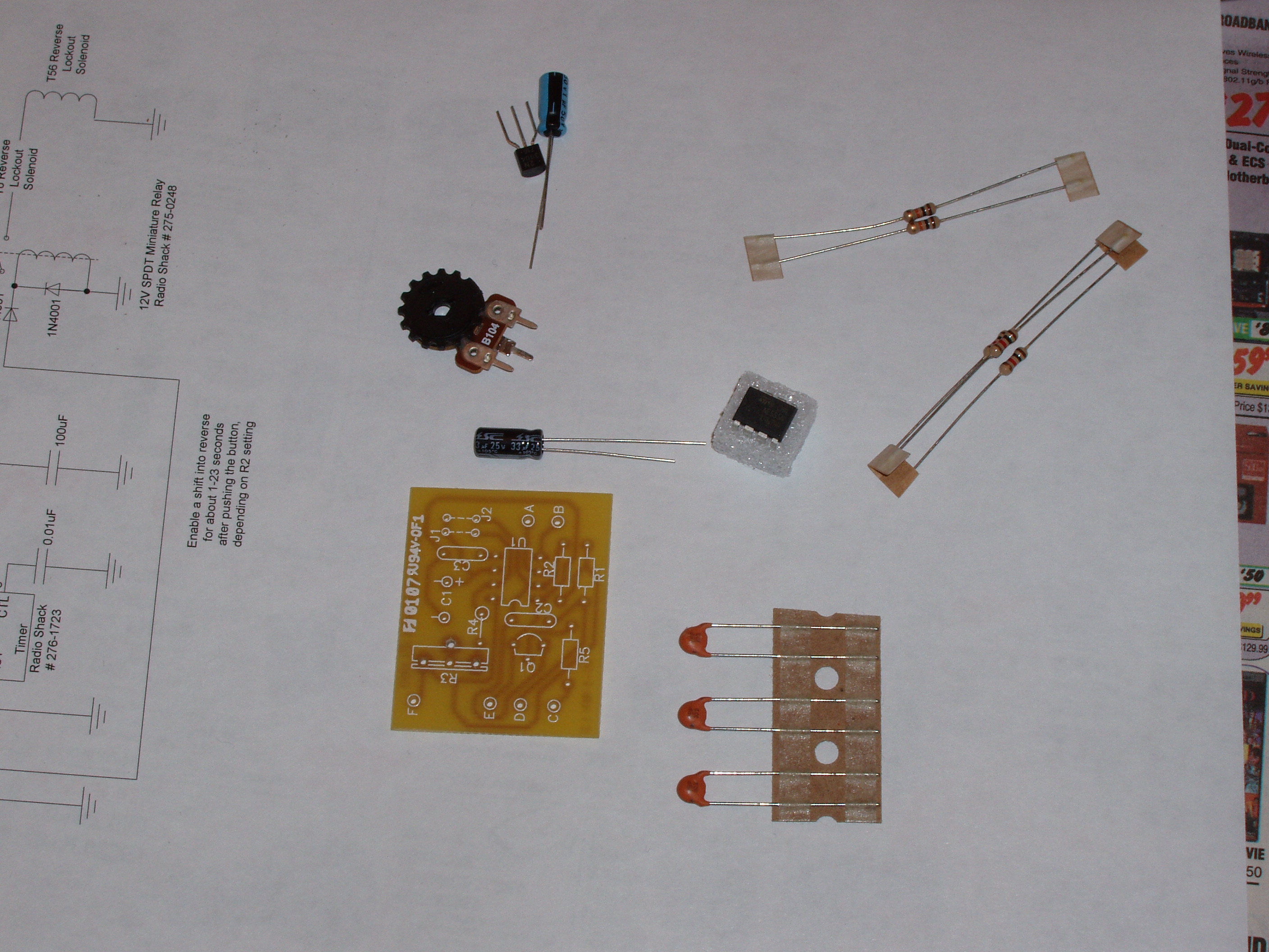
In order modify and finish the unit, I needed to also add
some additional components:
-
100uF electrolytic cap (25V should be fine.) for C1 (http://search.digikey.com/scripts/DkSearch/dksus.dll?Detail?name=P970-ND)
-
3-1N4148
diodes (http://search.digikey.com/scripts/DkSearch/dksus.dll?Detail&name=568-1360-1-ND)
- 47K Ohm
resistor (1/8W or larger) for R4 (http://search.digikey.com/scripts/DkSearch/dksus.dll?Detail?name=OD473JE-ND)
- Momentary
On pushbutton switch (one you like the looks of in the location you choose)
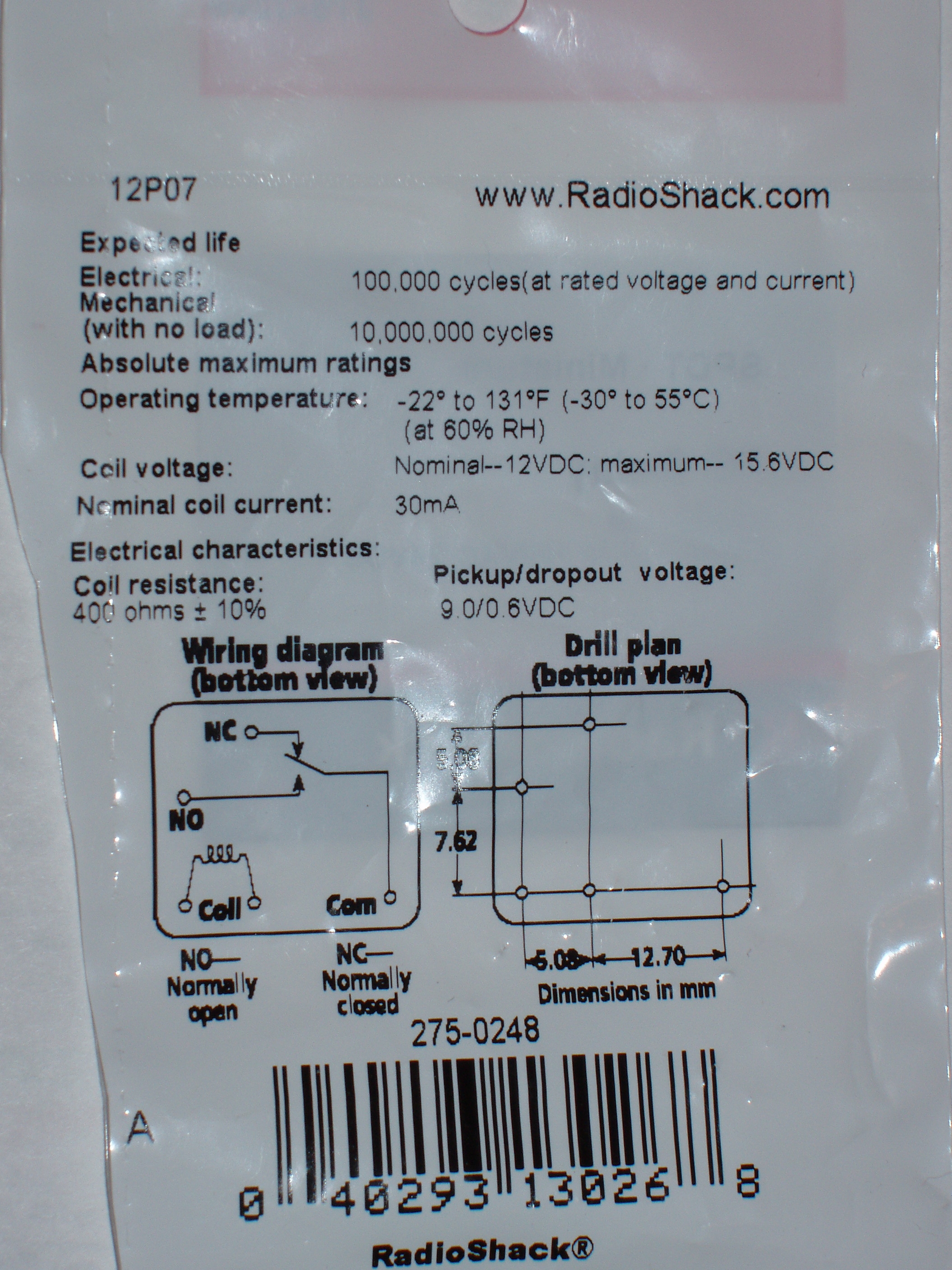
- 12V SPDT
Miniature Relay (Radio Shack # 275-0248) (http://www.radioshack.com/product/index.jsp?productId=2062482&cp)
- Small
plastic project box. (PacTec Model HM-9VB-ET) (http://www.mouser.com/Search/ProductDetail.aspx?qs=pUdSoVDiEjDQg3l9QgQNmA%3d%3d)
- Some
colored 18 gauge hookup wire
The time that the unit will hold the solenoid open is determined by the equation: Time (in seconds) =1.1 x C1 (in uF) x 0.000001 x (R3+R4) (in Ohms).
The UT5 kit comes with potentiometers that could be from 100K Ohms to 250K Ohms. Mine came with a 100K Ohm pot.
Since mine came with a 100K Ohm pot, the longest time interval I could get using the 1K Ohm R4 that came with the kit is T= 1.1 x 100 x 0.000001 x 100,000 = 10 seconds max, almost 0 minimum. This would probably be ok, but I decided that I would prefer a range of 5 to 15 seconds. That is why I replaced the 1K Ohm R4 with a 47K Ohm resistor, which gives me a (R3+R4) range of 47K to 147K Ohms, with a resulting range of about 5 to 15 seconds.
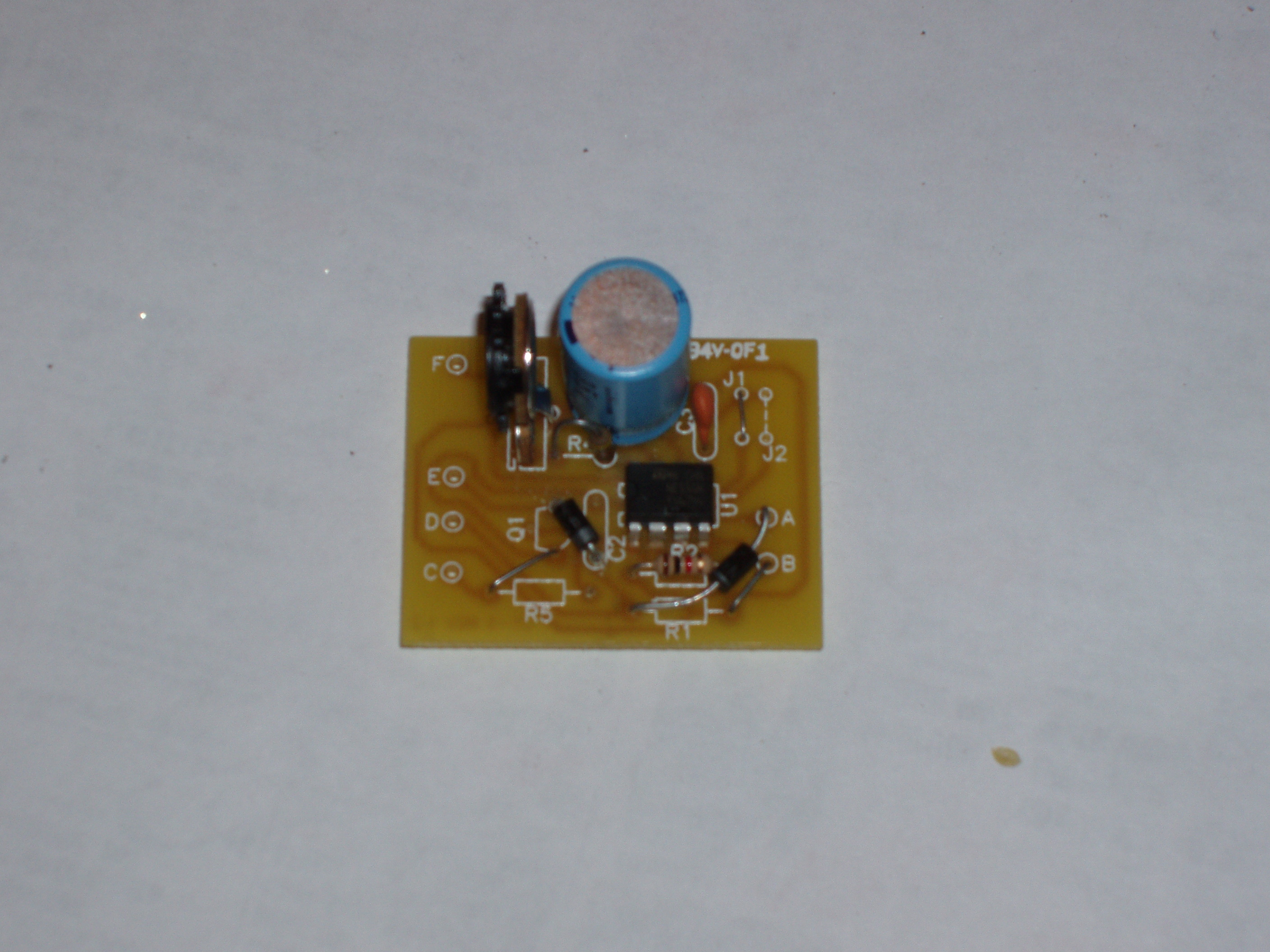
I had to ream some of the holes in the PCB out a bit with the tip of an Exacto knife in order to get some of the leads to go through the board.
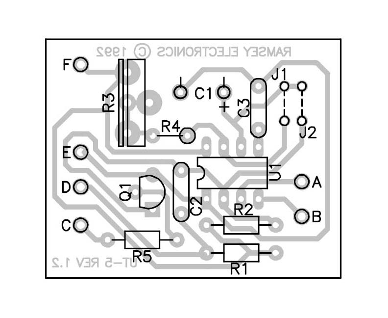
I soldered the components to the board. R3 was stock from the kit, R4 was 47K Ohms, C1 was 100uF and C3 is the stock 0.01uF cap that came with the kit. J1 is jumpered and J2 is not jumpered. U1 is the 555 Timer chip and is installed at U1. R2 is stock 10K Ohm resistor from the kit. Point B is jumpered to +12V at R1. The C trace at R5 is jumpered to the square pad of Q1. One diode is connected between Point A and the D trace end of R1. Make sure the diode band is on the R1 side of the diode, not the Point A side. This diode goes from the Q1 pad opposite the square pad and the D trace side of C2, with the band oriented towards C2. These diodes protect the 555 circuit from discharge current from the relay coil. The third diode needs to go across the output wire that goes to the solenoid, and ground. That diode is not on the PCB. The green below indicated the modifications I made.
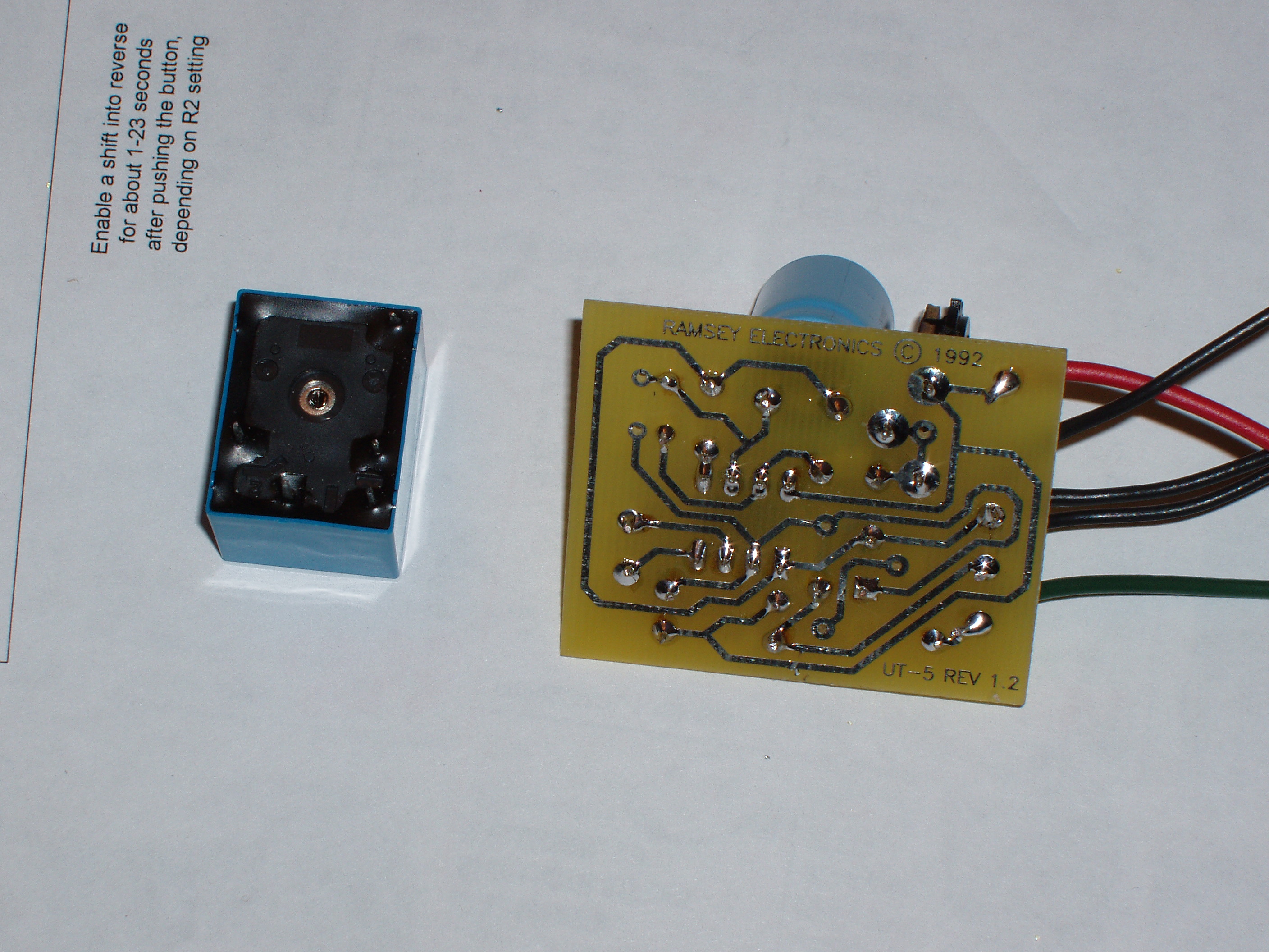
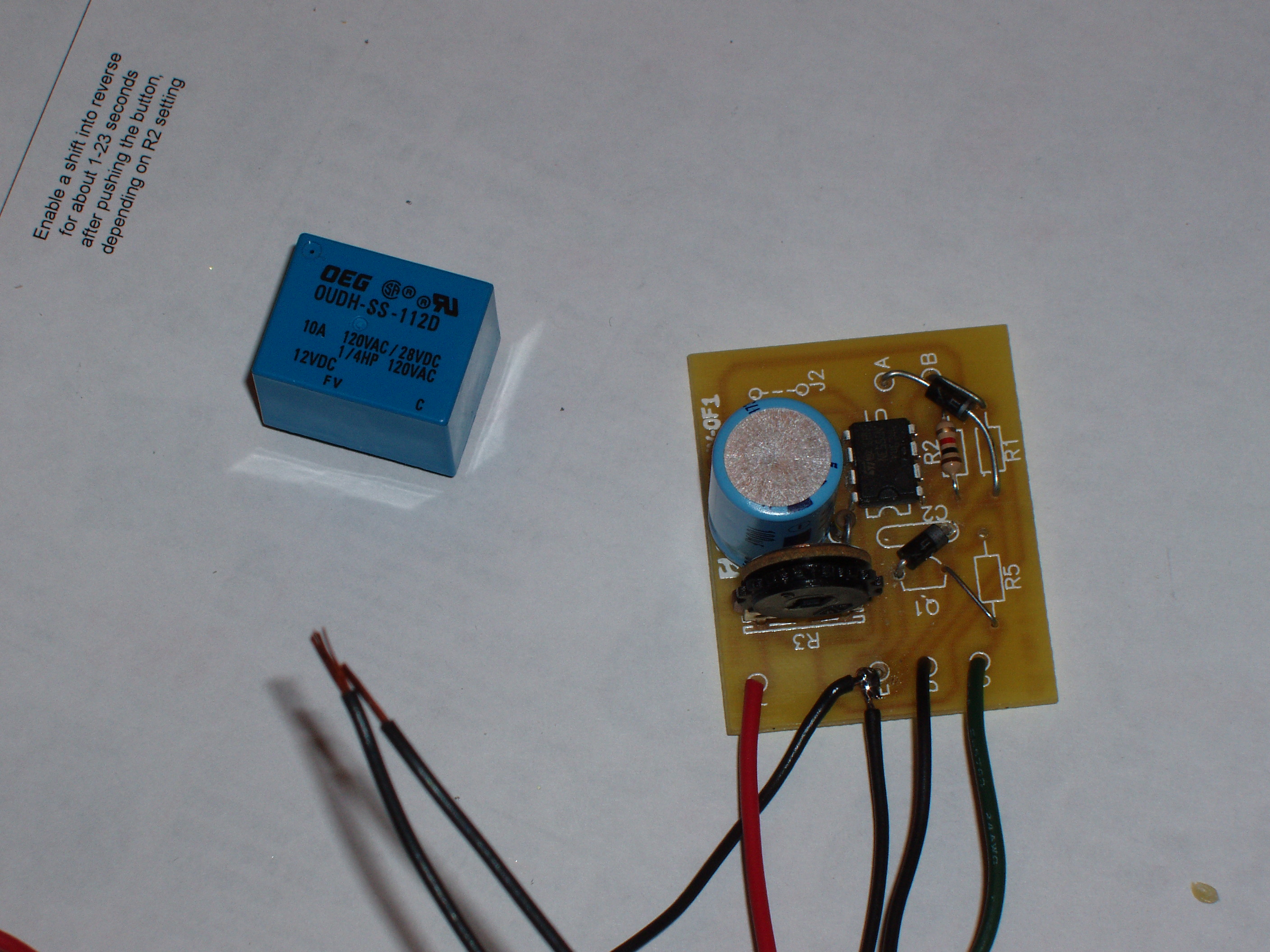
I soldered the wires between the board and the relay. I tested the circuit and it worked as advertised.
I drilled holes in the plastic project box for the wires, tied knots in the wires for strain relieve and closed the plastic box and the unit is done and ready for installation.
I set the resistor so the reverse lockout solenoid will be energized for about 10 seconds after I press the button. This gives me plenty of time to get shifted into reverse, but will allow the lockout to work during normal driving.
Installation
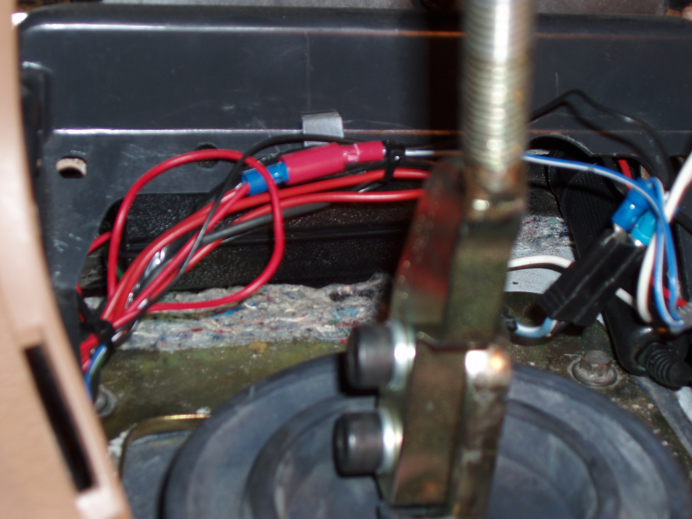
Here it is installed. With the box I chose from Fry's (it is the box made for use with a 9V battery, but I put the relay in the battery compartment), it slides right under the plastic plate behind the shift boot bezel and on top of the carpet backing. You have to push down on the carpet backing a bit to get it to slide under the metal bar, but it fits nicely.
Switch Installation
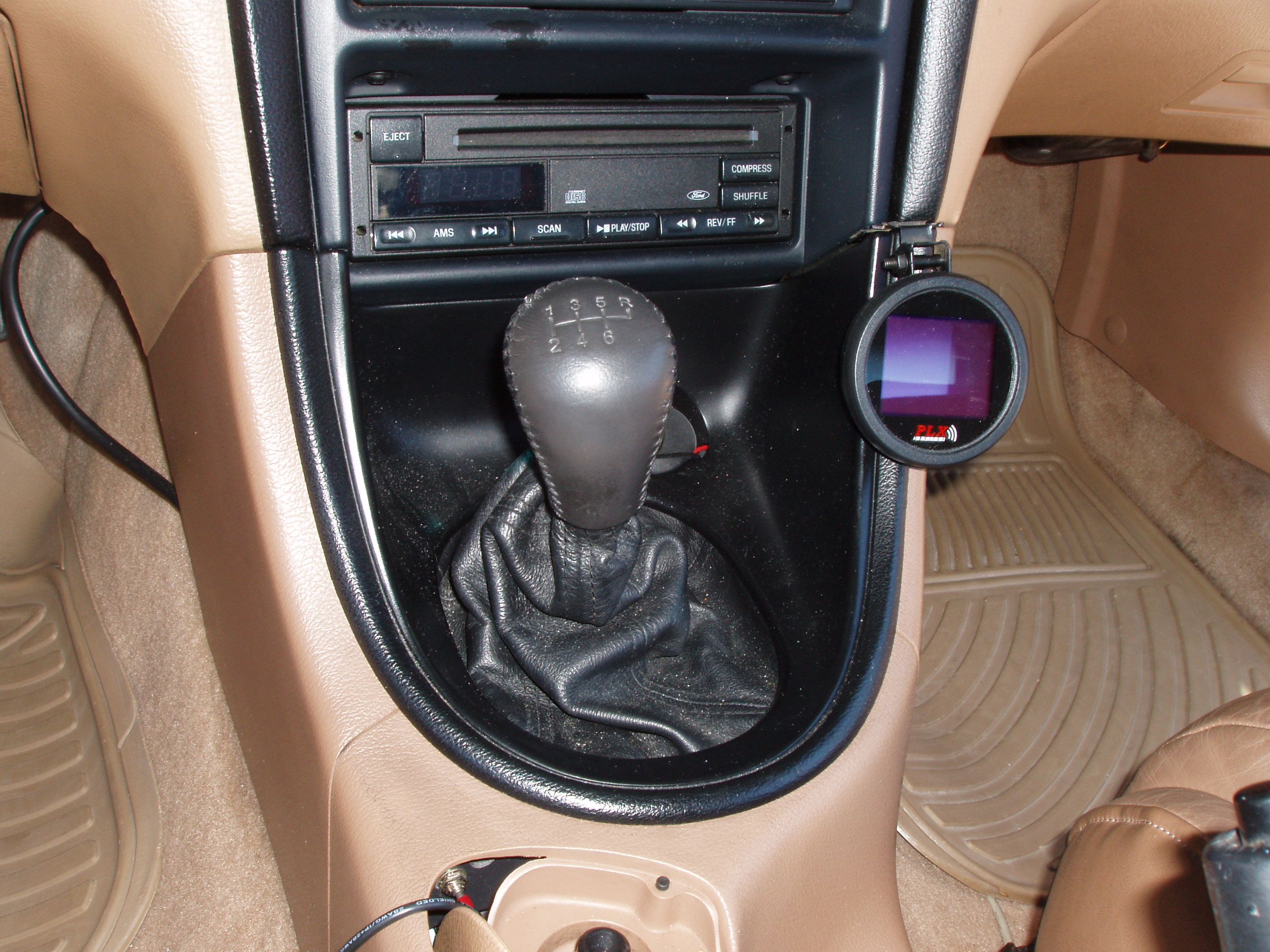
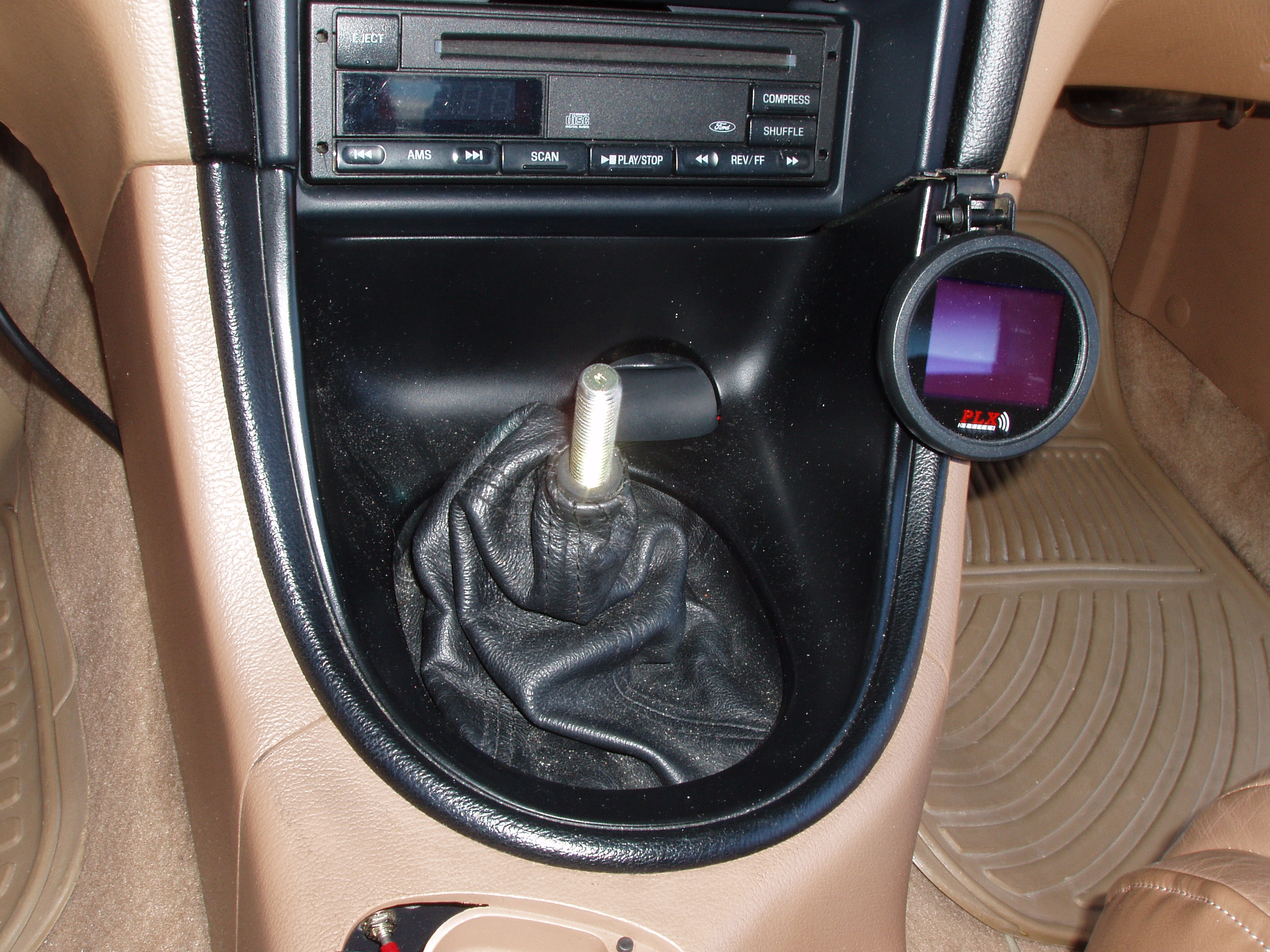
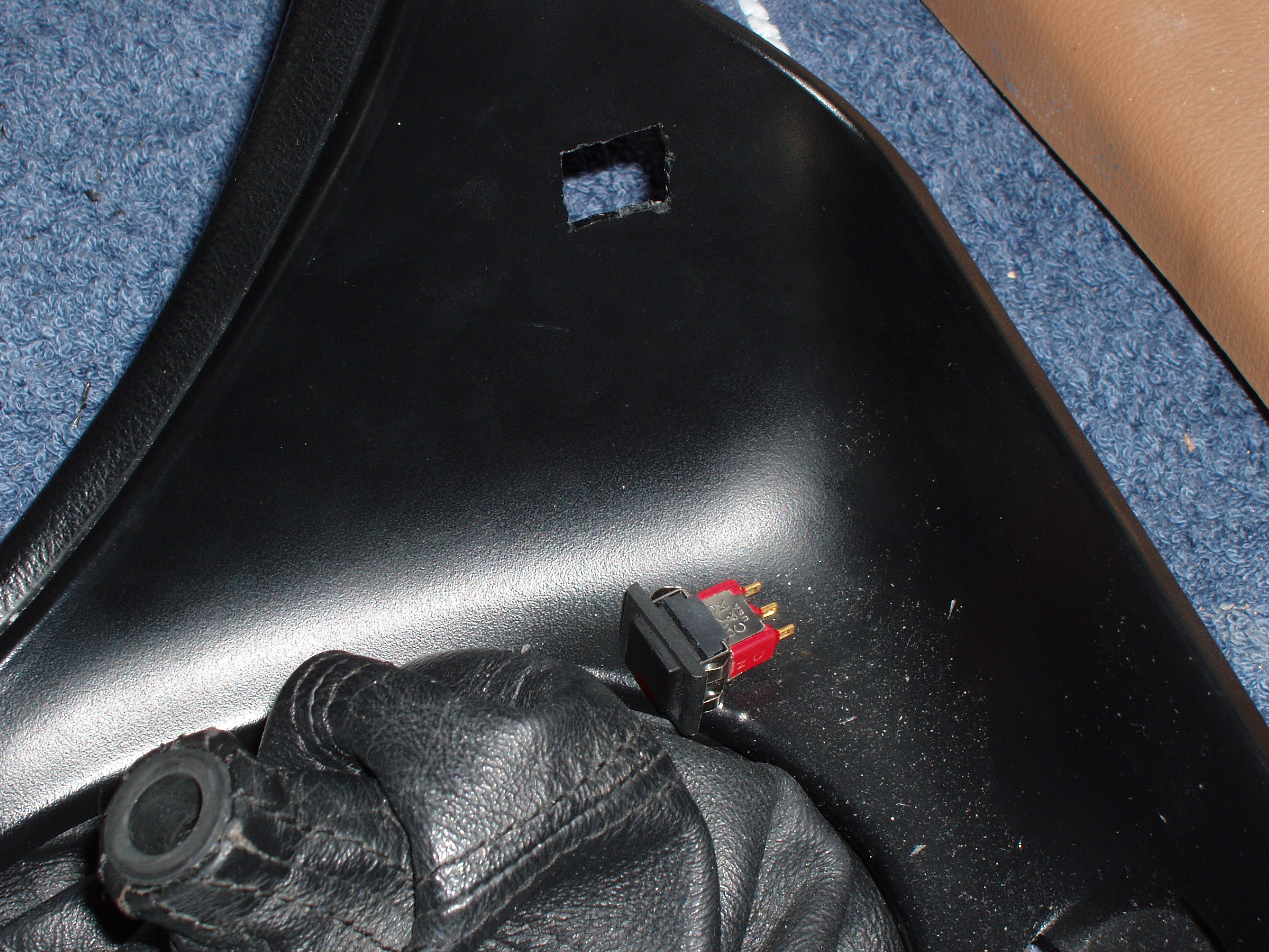
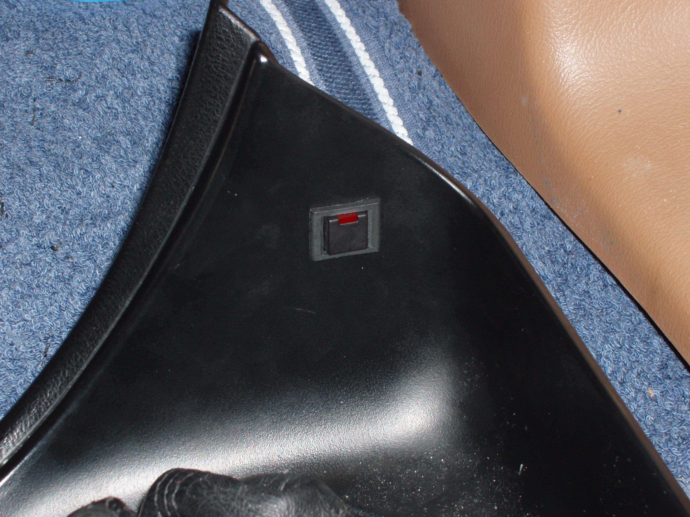
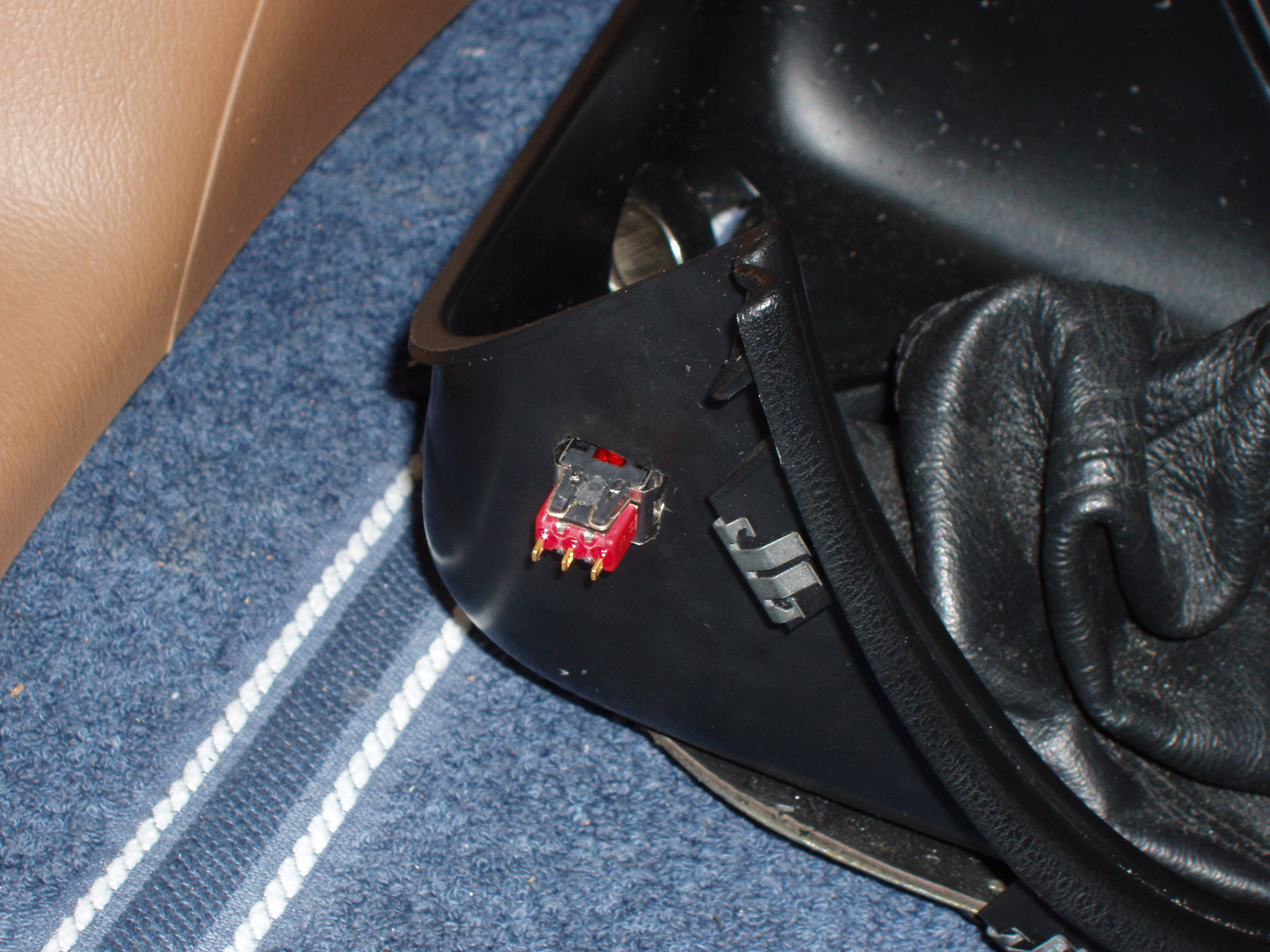
I decided to put the switch into the shift boot bezel. In order to do that, I needed to pull the shift knob and the shift boot/bezel.
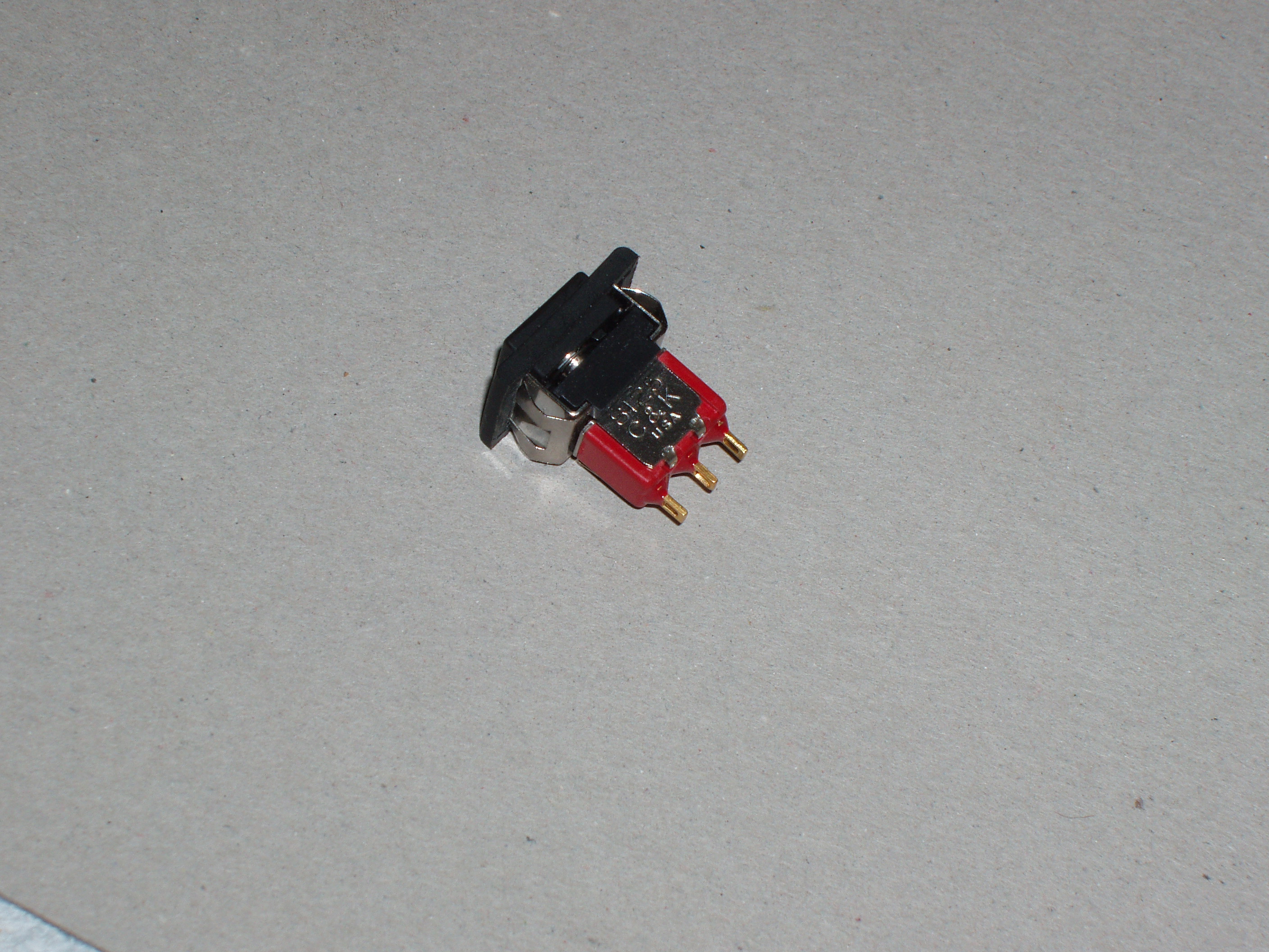
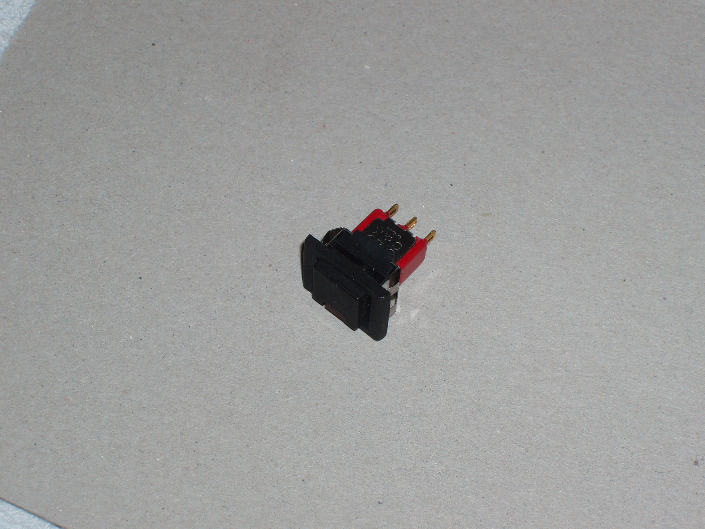
Here is the new pushbutton switch I chose. It required a rectangular hole be cut into the shift boot bezel.
I have been using this for over 2 years now, and I love it.