How to delete the Mach 460 CD deck, and add an aux input.
I decided to eliminate the Mach 460 CD deck in my '96 Cobra to make way for a DIN gauge pod, but I actually embedded my PLX M300 wideband into the old CD deck instead. Unfortunately, with the Mach 460 system in the '94-98 Mustangs, the audio signal from the radio runs through the CD unit, so removing the CD unit disables the radio. Most people replace the entire stereo system which is a huge pain in the butt, and expensive, and then the radio doesn’t look stock. I am happy with the radio, but I also wanted to add a connector so I could listen to my Apple iPod through my Mach 460 system. So I had to reverse engineer the signals between the radio unit and the CD unit. I figured out how to eliminate the CD unit while retaining use of the stock radio and I figured out how to add a switch to enable other audio devices such as my iPod to be played through the system.
I found a lot of good information about the Mach 460 system at: http://www.flemworld.com/Mach460/mach.html including the schematics of the sound system. The problem is that the connector pinouts are not shown, and many of the signals are not described.
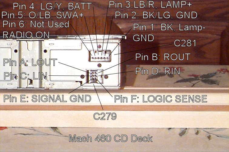
I bought two dead CD decks to use as donors. I dismantled one of them, removing the connectors and the control circuit board. Fortunately, the circuit board silk screen contained the signal names for all the pins on both connectors. From that information, I was able to trace back from the circuit board to the external pins of the CD deck. I have marked the signal names on a photograph of the back of the CD deck. (See below.)
At this point, I feel compelled to warn you to use all this information at your own risk. If you do what I do, and burn out your electronics, or even catch your car on fire, I am not responsible. (Late flash, I accidentally wired the pins on the signal connector backwards, and fried the left output of my radio, so I had to buy a used one off Ebay. The good news is, it all works well now.)
Since the schematics tell the signal names for most of the signals for connector C281, I was able to tell what the number of each pin is per the Flemworld schematics. None of the signals for connector C279 were named in the schematics, so I labeled them A through F.
The pins for the connector C281 are numbered 1-6 from the right when looking at the back of the deck. The following table describes the signals for each pin:
Pin Wire-color Signal-name Signal-description
1 BK LAMP- Ground for the CD deck lights 2 BK/LG GND Power Ground for the CD deck 3 LB/R LAMP+ 0-12V power for CD deck lights 4 LG/Y BATT 12V Power for CD deck 5 O/LB SWA+ 12V from radio, when in run or acc mode 6 Not used RADIO ON Not used
I numbered the pins for the connector C279 from A to F, right to left, top to bottom when looking at the back of the deck. Since my cable was well shielded, and I didn’t dismantle it so I don’t know the wire colors. The following table describes the signals for each pin:
Pin Wire-color Signal-name Signal-description
A ? LOUT Left audio OUT B ? ROUT Right audio OUT C ? LIN Left audio IN D ? RIN Right audio IN E ? SIGNAL GND Signal ground F ? LOGIC SENSE Tells the radio the CD deck is active
Using the connectors from one of the donor CD decks, I made a breakout box that allowed me to look at the action of each signal, cut signals and patch signals so that I could characterization of the interface to the CD deck. Since I did not have a spare set of female connectors for the CD end of the breakout box cable, I used 11 female connectors from a Honda OBD0 ECU connector with shrink wrap tubing around each connector to keep them from shorting together. This allowed me to intercept all the signals between the radio and the CD deck without cutting either existing cable.
The following is a discussion of what I learned about each pin during the characterization process:
Connector C281:
Pin 1, LAMP-: This pin is the ground pin for the lamps in the CD deck. Sony must have thought that it would be better to have a separate ground for the illumination lights. You can use this connector for the ground wire for the illumination for the gauges in the DIN gauge pod.
Pin 2, GND: This pin is the ground pin for the CD Deck power circuits other than the illumination lights. This pin can be used for ground if you are replacing the CD unit with some other audio device.
Pin 3, LAMP+: This pin supplies the illumination lights with +0 to +12V depending on where the interior illumination pot on the light switch. This voltage is only present when the park or head lights are on. You can use this connector for the power wire for the illumination for the gauges in the DIN gauge pod.
Pin 4, BATT: This pin supplies +12V straight from the battery (fused) to the CD deck at all times. This is the main power supply to the unit. This pin can be used for power if you are replacing the CD unit with some other +12V audio device.
Pin 5, SWA+: This pin supplies +12V to the CD deck whenever the starter switch is in Accessory Mode or Run Mode. This signal is supplied through the radio, so I do not know how much current you can count on from this signal, without damaging the radio. Use this signal with care. Late flash: From experience, this signal does not supply enough current to drive a typical 12V relay.
Pin 6, RADIO ON: Per the Flemworld schematics, this pin is not wired externally to the CD deck.
Connector C279:
Pin A, LOUT: This pin carries the Left audio OUT of the CD deck, into the radio. This input to the radio is not line-level. I patched in the earphone signal from my old Intel MP3 player and a borrowed Archos MP3 player into this signal and the corresponding right one. I had to put the volume of the Intel MP3 player up almost to the max in order for the MP3 music to come close to the volume I get from the radio. It was still much quieter than the radio, but it was livable. The Archos player had more drive, so it was able to drive the amplifier without the volume of the Archos player having to be as high as the Intel player did. My iPod works in a similar way to the Archos player. Your results may vary. A good stereo shop could probably help you with an appropriate level-shifting pre-amplifier if you are fussy. If the radio is in radio mode (not CD mode), and you unhook the LIN and RIN signals described below, and apply a different audio signal to LOUT and ROUT, the different audio signal will play, such as from the iPod. The radio still indicates the frequency it is tuned to, and the radio is not disabled, but the radio signals have been unhooked so you can’t hear them. You can use this characteristic to just switch in an alternative audio source if you wish to retain the CD player and add some other audio device.
Pin B, ROUT: This pin carries the Right audio OUT of the CD deck, into the radio. It has the same characteristics of LOUT.
Pin C, LIN: This pin carries the Left audio IN to the CD deck, from the radio. The audio comes from the radio whenever the radio is enabled. This audio loop through the CD deck is the reason why the CD deck is needed in order for the CD deck to work. If you want to take your CD deck out and use the DIN slot for some other purpose, you can short LIN to LOUT and RIN to ROUT, and your radio will still work without the CD deck in the circuit. None of the others pins need a connection, but you need to ensure they don’t accidentally short to ground or each other if you don’t use them. If you want to use your radio and add an auxiliary input, you will need to add a DPDT switch or relay for each channel.
Pin D, RIN: This pin carries the Right audio IN to the CD deck, from the radio.
Pin E, SIGNAL GND: This pin is the ground for all the audio signals being carried between the CD deck and the radio. It is also the ground for the LOGIC SENSE signal described below.
Pin F, LOGIC SENSE: Use this information in particular at your own risk. Without knowing the current characteristics of the LOGIC SENSE input to the radio, is could damage your radio very easily if you are not very careful with this signal. This pin is normally almost at 0V with or without the CD deck connected to it. When a CD is in the CD deck, the CD deck pulls this pin up to +5V. When the radio sees the +5V signal, it does two things. First, it turns off the radio do no radio audio signals come into the deck on LIN and RIN. Second, it changes the radio display from the radio frequency to “CD”. I used a bench +5V supply and a series of consecutively smaller resistors to learn that a pullup resistor of 1K ohms would not trigger the radio to switch, but a 500 ohm resistor will. You are on your own if you want to use this signal to switch the system to your new auxiliary input.
I have actually hooked up a couple of MP3 players to this circuit, including my iPOD with a Belkin RF remote control, and they work great.
If you just want to eliminate the CD player, pull the C279 connector out of your CD player, and wire LIN to LOUT and wire RIN to ROUT, and your radio will work.
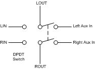
If you want to add a switch, you can switch between the radio and an external device. Use a DPDT switch. Wire LOUT & ROUT to the center lug of each pole of a DPDT (Double Pole, Double Throw) switch. Wire LIN & RIN to one side each pole of the switch and wire the left and right audio signal of the auxiliary device to the other side of each pole.
I have since replaced this switch with a relay that is controlled by an extra fog-lamp switch I put in place of the coin holder in my console.
If you want to use the CD illumination power to power the illumination of the gauges in the DIN gauge pod, just wire up the LAMP+ and Lamp-GND signals to the Gauge illumination wires.
Have fun.